The Tesla Coil and its quirky creator
The term ‘mad scientist’ could apply to Nikola Tesla. Perhaps he is the very source of it. He barley slept, sat down for dinner at exactly 8:10PM every night, and once spent a small fortune nursing his beloved pigeon back to health. All the while, Tesla’s contributions to science and engineering are matched by few. He patented hundreds of weird and wonderful inventions, some of which being very commercially fruitful – the AC induction motor to name one. There is good reason a certain modern car maker chose to be Tesla’s namesake.
The Tesla Coil is another iconic invention by Tesla. It may not have much practical use today, but has remained noteworthy because of the dazzling electric show it creates. It’s also a great exhibit for electrical engineering theory.
The Tesla Coil is a resonant transformer that outputs power at ultra-high voltage – as much as several million volts! With this comes the vivid ionizations of air, otherwise known as sparks. The sparks of the Tesla Coil can arc amazing distances and with a hyperactive intensity.
How the Tesla Coil works - key principles
Transformers
Transformers use Faraday’s law of induction to step up or step down voltage. They consist of two coils near each other. When power is applied to one, a magnetic field is made and induces power in the opposing coil. The number of coil turns of each determines the output voltage.
An ideal transformer will step up or step down voltage according to the following formula:
VSC = VPC x (NSC / NPC)
Where:
- VPC is the voltage in the primary coil
- VSC is the voltage in the secondary coil
- NPC is the number of coil turns in the primary coil
- NSC is the number of coil turns in the secondary coil
For example, let’s calculate the output voltage in the scenario:
- Input voltage = 240V
- Primary coil turns = 4
Secondary coil turns = 8
VSC = 240 x (8 / 4)
VSC = 480 Volts
As you can see, voltage increases greatly depending on the number of coil turns used. Because power remains constant through the process, the current lowers as voltage is stepped up and vice versa (power = voltage x current).
Electrical resonance
Imagine pushing someone on a swing. If you push too early or too late at each return interval, it’s hard to get the swing going. But if you push the swing exactly at its peak, it’s easy to reach higher heights with each push. This perfect timing of pushes is an example of resonant frequency.
Just like the swing, resonant frequency applies to electricity. Achieving resonance during a transfer of power allows the process to be efficient.
An example are LC circuits – L denoting ‘inductor’ and C denoting ‘capacitor’. Inductors are coils that make magnetic fields and capacitors are devices that store and discharge electrical charges. If an inductor and capacitor are arranged in a circuit and are perfectly tuned, the following happens:
- Power flowing through the circuit charges the capacitor. When the capacitor is fully charged, it discharges and supplys power to the coil.
- The power flows through the coil until all the charge from the capacitor is used. During which, the coil produces a magnetic field.
- The magnetic field induces a voltage back through the coil but in the opposite direction. The voltage charges the capacitor back up and the magnetic field fades out just as the capacitor is about to discharge again.
- As the capacitor and coil are resonantly tuned (like the person pushing the swing), the cycle continues over and over. In an ideal scenario, the cycle would continue forever. In reality, other resistive forces eventually bring the cycle to an end.
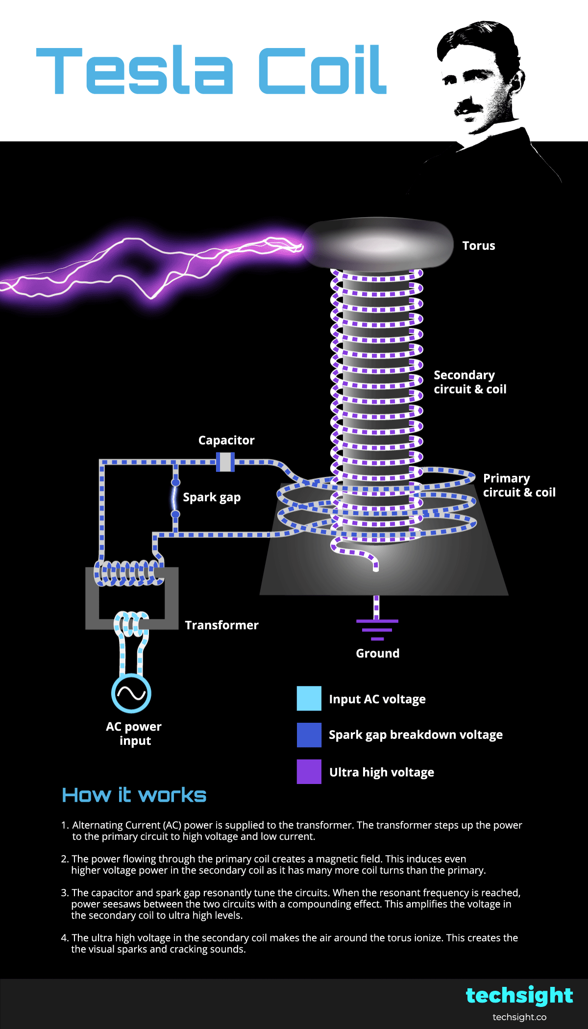
How the Tesla Coil works - animated schematic steps
Alternating Current (AC) power is supplied to the transformer. The transformer steps up the power to the primary circuit to high voltage and low current.
The power flowing through the primary coil creates a magnetic field. This induces even higher voltage power in the secondary coil, as it has many more coil turns than the primary. Secondary coils often have hundreds of turns, but less are shown in this schematic for clarity.
The capacitor and spark gap resonantly tune the circuits. The capacitor charges fully and then discharges with the spark gap breakdown voltage. The spark forms an LC circuit and allows power to seesaw resonantly between the primary and secondary circuits with a compounding effect. This amplifies the voltage in the secondary coil to ultra high levels.
The ultra high voltage in the secondary coil makes the air around the torus ionize. This creates the visual sparks and cracking sounds.